
Description of the Mobile Lab
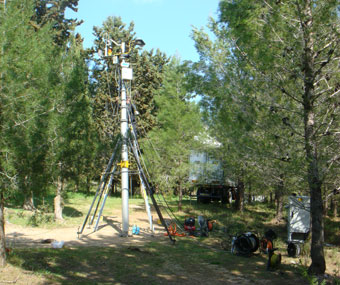
The measurement platform of the 'ecosystem mobile observation system' is housed on a 12-ton four-wheel drive (4x4) pneumatic air suspension truck frame (MAN TGL 10.180.BL). It hosts a pneumatic mast with complete EC system that can be detached from the truck, and provide an air-conditioned enclosed facility (leveled and stabilized pneumatically), with racks for instrumentation, workbenches, computer desk, wireless and cellular communication. It is electrically independent, using a generator and a uninterrupted power supply (UPS) system (the entire unit was constructed jointly with Girsh Industries, Ashdod, Israel). When deployed, the truck (lab), mast, and generator are meant to form an equilateral 35 m triangle, minimizing the interference among the three components. The main components of the EMOS are briefly described below:
-
The Electrical System
 Analytical instruments are powered through a UPS system comprised of 600 Ah, 24 V batteries bank, high efficiency 24V DC to 220V AC convertor (up to 2200W; ST2500, Cotek, Taiwan). The UPS system is charged on demand based on the batteries’ voltage by two automatic chargers (40 Amp each; A. Ben Ari, Israel). Charging can be provided either by wall hookup, or using the dedicated 18 KVA, 3 phases, diesel generator (LPW Engine, Lister Petter, UK), which can be deployed in a distance of up to 35 m from the laboratory (and up to 60 m from the measurement mast).
Both fuel tubes and electric cables are rolled underneath the truck frame. The truck is fitted with two fuel tanks (400 L, combined) supplying fuel for both the truck and the generator, allowing up to ~200 h of generator operation time for maximal demand, but much longer when used intermittently to charge the UPS system. Refueling is done using transportable fuel drums, and a 12 V fuel pump installed on the truck. A specially designed electrical control box in the laboratory cabin provides a ‘floating’ electrical system supplying 220, 12, and 24 volts power supply, controls of the generator and chargers, full fluorescent or low power led lighting, and monitoring of the power level and consumption.
-
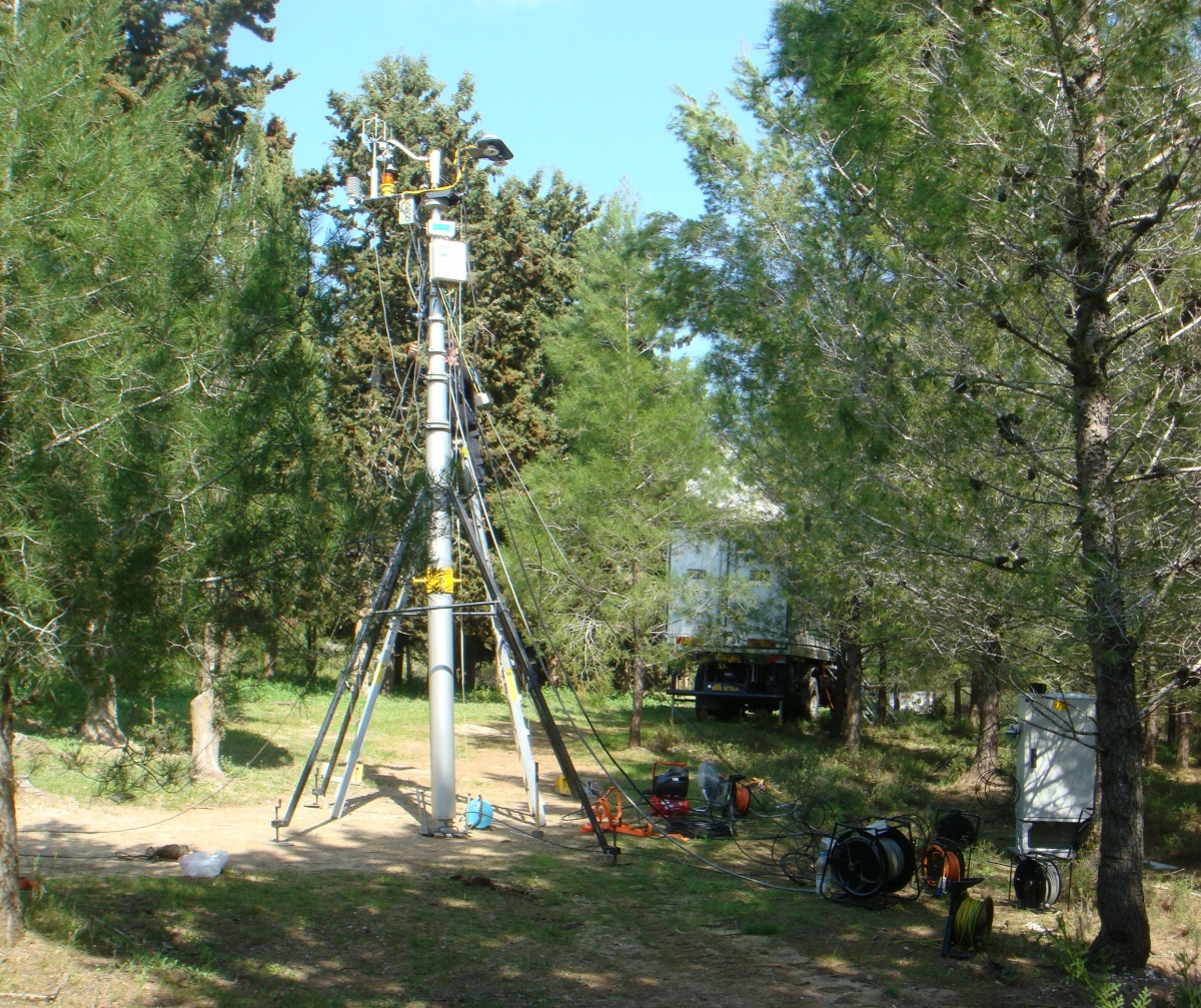
The Telescopic Mast
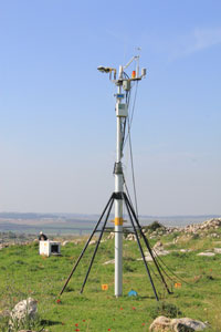 We used a 4-28 m 10-sections telescopic pneumatic mast operated by a 220 V 6 L compressor and pressure-regulating valve (Super Heavy Steady, CX.7009.NA_4; Fireco Components, Italy). The mast is stored vertically on a custom trolley inside the lab and pulled out and turned vertically on a special pneumatic fork for positioning and leveling in the designated measurement site. A folding platform with access steps could also be rolled out of the back of the truck at a 2.5 m height to facilitate installation and maintenance of instrumentation at the top of the mast before full extension.
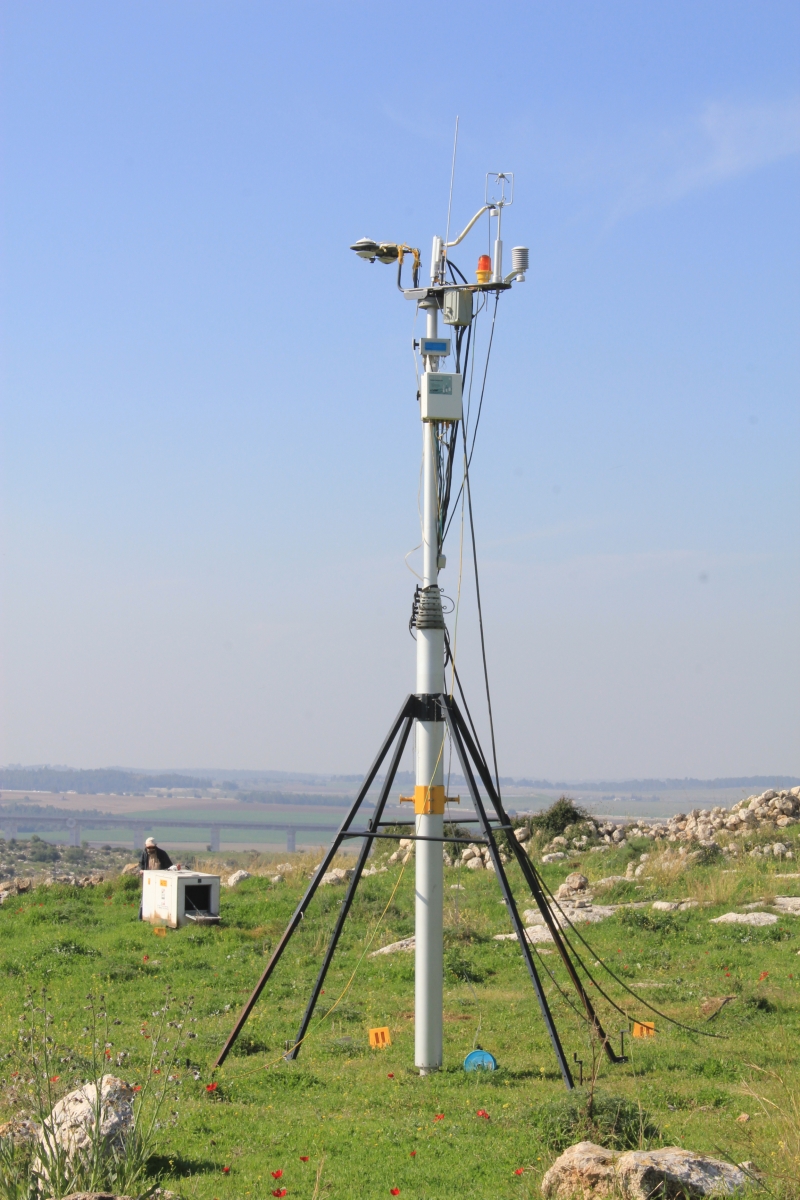
Following the extension, the mast is stabilized with a 4-leg assembly and three sets of guy ropes. The mast is then self supported and detached from the track, except for sample tubes and cables connected between the mast and instrumentation in the lab. The top of the mast is supplied with 24 V power line, wireless communication, a lightning surge rod, and an aircraft warning light.
-
The Laboratory
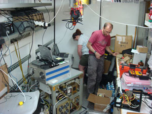 The dimensions of the custom made cabin installed on the truck frame are .43x2.53x2.3 m (width, length and height respectively; 65 mm insulated walls and 100 mm insulated roof and floor). It is designed to accommodate laboratory equipment and working conditions. Temperature control is provided by fans and/or air-conditioning unit (1.5 HP, Electra Ltd, Israel). The internal design of the lab is schematically shown in Figure 1. It includes space for up to 4 standard 19” racks (48.26 cm) on one side, a standard working bench with drawers and shelves, and wash sink with fresh water supply (150 L supply and collection system) on the other side, and 3 sits computer desks at the front end. Designated secured equipment storage space is at the backward part of the cabin, expandable by folding a section of the working bench. This space includes also a moveable crane attached to the ceiling, extendable outside the back of the truck for equipment handling, and it houses the folding platform for the mast handling (see above). A designated casing beneath the working benches houses the trolley with the folded and horizontally inserted mast (~4 m).
Between the laboratory cabin and the truck driver cabin, a purpose built deck (0.8x5.6 m) housing the A/C unit, battery bank, fresh water tank, as well as a manifold of four compressed gas cylinders (connected via polished stainless steel tubing to a valve manifold inside the lab). The deck is equipped with a second crane and special cage to handle the compressed gas cylinders, and provides ladder access to the roof of the lab cabin. About half of the roof of the laboratory cabin is adapted as a working platform, enclosed within a folding safety rail. Access to the lab and deck is via two sets of steps (0.8 m wide) that can be folded and slid underneath the truck frame during transport. The frame also holds a number of utility boxes, and a special ‘drawer’ that houses the generator.
-
Measurement systems
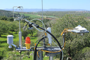 Key measurement instruments, including sonic anemometer, gas analyzers, meteorological instruments and air intakes for analytical instruments housed in the laboratory, are installed on the mast using a custom made rotating support rack connected at its top (Figure 2). The rotating rack’s structure is designed first, to allow direction adjustment and leveling (using the sonic built inclinometer and the guy cables), and second, minimize interference between different instruments and sensors.
Flux measurements rely on an EC system that provides CO2, H2O, sensible and latent heat fluxes using a 3D sonic anemometer (R3-100; Gill Instruments, UK) and semi-closed-path CO2/H2O infrared gas analyzer (IRGA; LI-7200, LI-COR, USA) using 60 cm long tubing fitted with 2 μm filter in the inlet (F series, Swagelok, US), and data analyzed using EddyPro Software (LI-COR). The sonic, IRGA and Gill interfaces are linked via either network cable or wireless connection to a computer in the laboratory for data storage and communication to the home lab. In addition to the EC system, meteorological parameters, such as pressure, air temperature and relative humidity (HMP45C probes; Campbell Scientific, Utah) and pressure (Campbell Scientific, USA) were measured and logged. Two identical sets of radiation sensors (Kip & Zonen, The Netherland) are installed in the up and down facing parts of the special rack (Fig 2). These sensors include solar radiation (0.285-2.80 μm; CMP21), long-wave radiation (4.5-42 μm; CGR4); and photosynthetic active radiation (PAR, 0.4-0.7 μm; PQS1).
All sensors are connected using differential mode via a multiplexer to a data logger (CR3000, Campbell Scientific, Utah) and together with the IRGA’s air pump are located in a weather-box at the bottom of the mast. The top of mast rack also houses the inlet and associated filters for all additional gas analyses carried out in the laboratory unit. Inlets were spaced around that of the IRGA to optimize location vs. the sonic and minimize interference. To shorten their lengths, auxiliary tubing were suspended directly to the lab. These tubing served during the first two years of operation instruments, such as proton reaction mass spectrometer (PTRMS) for volatile organic compounds (VOC) flux measurements (Seco et al., 2013), quantum cascade laser for carbonyl sulfide flux measurements (Asaf et al., 2013), ozone concentrations, isotopic analysis, and particle analyzer (unpublished).